|
GSM |
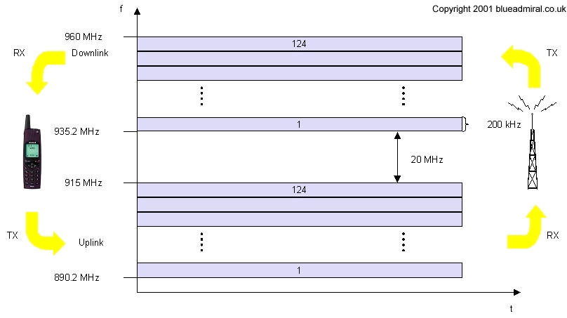
Radio Air Interface One of the most interesting interfaces in the GSM network is the Um, the Radio Air Interface because it comprises many of the mechanisms used for multiplexing and media access. GSM utilises SDMA (Space Division Multiple Access) using cells with BTS and assigns an MS to a BTS. What's more, FDD (Frequency Division Duplex) is used to separate the downlink and uplink as shown in Figure 5.
Figure 5 Frequency
division multiplexing for multiple access and duplex Media access combines TDMA and FDMA. In GSM 900 there are 124 channels, each 200KHz wide and are used for FDMA, however in GSM 1800, there are 374 channels used. The following is an example based on the GSM 900 system, while figure x.iii shows the FDM in GSM. Figure 6 shows TDM in use. Each if the 248 channels is additionally separated in time by using a TDM GSM frame. i.e. each 200 kHz carrier is subdivided into frames that repeated continuously. The duration of a frame is 4.615 ms which is subdivided into 8 GSM time-slots, where each slot represents a TDM channel and lasts for 577 ms. Hence each TDM channel occupies the 200 kHz carrier for 577 ms every 4.615 ms. Data is transmitted in small sections known as a 'burst' figure 6 shows a normal burst as used for data transmission inside a time slot. In this example (Figure 6) the burst is only 546.5 ms long and contains 148 bits of data. The remaining 30.5 ms is used as guard space which is done to prevent overlapping with other bursts due to the different path delays and to leave the transmitter time to turn on and off. However, if the full slot if filled with data that would allow the transmission of 148 bits within the 546.5 ms. So each physical TDM channel has a data rate of around 38.8 kbit/s, but each radio carrier transmits around 270 kbit/s over the Um interface.
Figure 6 GSM TDMA frame, slots, and bursts There are three bits at the start and finish of each burst these are known as the 'tail' and are set to 0 so they can be used to enhance the receiver performance. The training sequence in the middle of the burst is used to adapt the parameters of the receiver to the current path propagation characteristics and to select the strongest signal in the case of multi-path propagation (check this). The 'S' flag indicates whether the data field contains user or network control data.
|