|
Home
Home
Introduction
Historical Background
GSM
EDGE
WCDMA
UMTS
The Future
Final Thoughts
Blueadmiral.com
|
Handover
GSM systems require a
procedure known as a Handover to maintain the continuity of the call.
This is because a single cell does not cover the whole service area e.g.
a whole city or country. However a single cell has a maximum service
area of approximately 23 miles (35 km) for each antenna (Tripathi, et
al. 1998). The smaller the size of the cell and the faster the movement
of the MS through the cells (Up to 155 mph (250 kph) for GSM), the more
handovers of ongoing calls are required, but a handover should not cause
the a call drop. Basically there are two main reasons for handovers,
however the GSM Specification identifies 40 reasons.
The MS moves out of coverage of the serving BTS thus the signal level
becomes lower continuously until it falls beneath the minimal
requirements for communications. Or the error rate may grow due to
interference, the distance to the BTS may be do high. All these effects
may diminish the quality of the radio link and make transmission
impossible in the near future.
The wired infrastructure i.e. the MSC, BSC may decide that the traffic
in one cell is too high thus introducing congestion and hence decides to
shift some MSs to other cells with a lower level of traffic, if that is
possible. Thus, handovers can be used as a method of controlling traffic
through load balancing to relieve localised congestion.
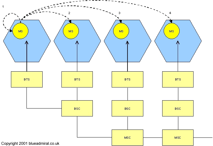
Figure 11 shows four possible handover scenarios with in the GSM system.

Figure 11 Types of
handover within a GSM system
1. Intra Cell Handover : This happens when within a cell, when
narrowband interference could make transmission at a certain frequency
impossible. The BSC could then decide to change the carrier frequency.
(1)
2. Inter Cell, intra BSC handover : This type of handover is a typical
handover within the GSM system and occurs when the MS moves from one BTS
to another but stays within the control of same BSC. The BSC performs
the handover and assigns a new radio channel in the new BTS, then
releases the old BTS. (2)
3. Inter BSC, Intra MSC handover : Since a BSC controls a limited number
of BTSs, the GSM system has to perform handovers between BSCs. This form
of handover is controlled by the MSC. (3)
4. Inter MSC handover : A handover could also be required between two
BTSs that belong to two different MSCs, now both MSCs perform the
handover together.(4)
In order to provide all the information necessary for a handover due to
a weak link, the MS and the BSC both perform periodic measurements of
the downlink and the uplink quality respectively. The link quality
measurement is made up from receive signal level (RxLev) and the bit
error rate (BER) and form part of the layer 3 messaging function.
Measurement reports are sent by the MS about every 0.5 seconds and these
contain the quality of the current link used for transmission as well as
the quality of certain channels in neighbouring cells (the BCCHs).
|

