|
Mobile Terminated Call
A simplified procedure for
a mobile terminated call
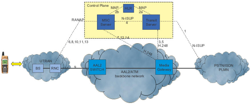
Figure 38 Mobile
Terminated Call (Traffic Case)
1 An incoming
call is received in the GMSC server
2 Routing data is obtained from the MSC server (VLR) via the
HLR
3 Resources controlled by the GMSC server are reserved in
the MGW
4 The call setup towards the visited MSC server is initiated
by the GMSC server
5 Through connection of the MGW resources is ordered by the
GSMC server
6 Paging of the called party is ordered by the MSC server,
the call setup is confirmed by the UE.
7 Resources controlled by the MSC server are reserved in the
MGW
8 The MSC server orders the RNC to setup a radio access
bearer
9 The user plane is setup from the RNC to the MGW
10 The RNC informs the MSC server that the user pane setup to the MGW
has been completed
11 The MSC server is informed by the UE that altering of the called
party has started
12 The MSC server orders the MGW to start sending ringing tone towards
the calling party
13 Answer is received from the called party
14 Through connection of the MGW is ordered by the MSC server
|